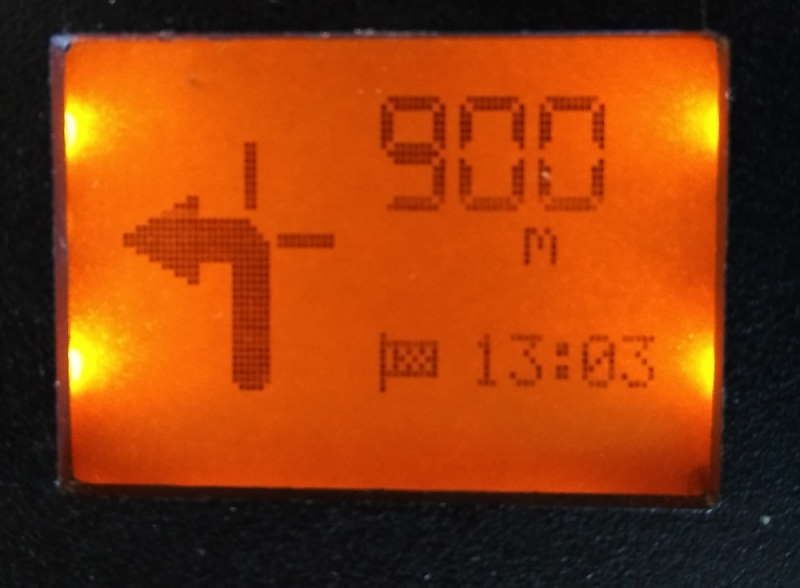
The goal of this project is to create a low cost display that can be mounted to the handlebars or fairing of any motorcycle to provide a display of the riders route navigation. GPS navigation is performed via an app running on the users smart phone. Directions are communicated over Bluetooth from the the phone to the display module discussed below. The display is designed to be minimally distracting and provides the following information to the rider: 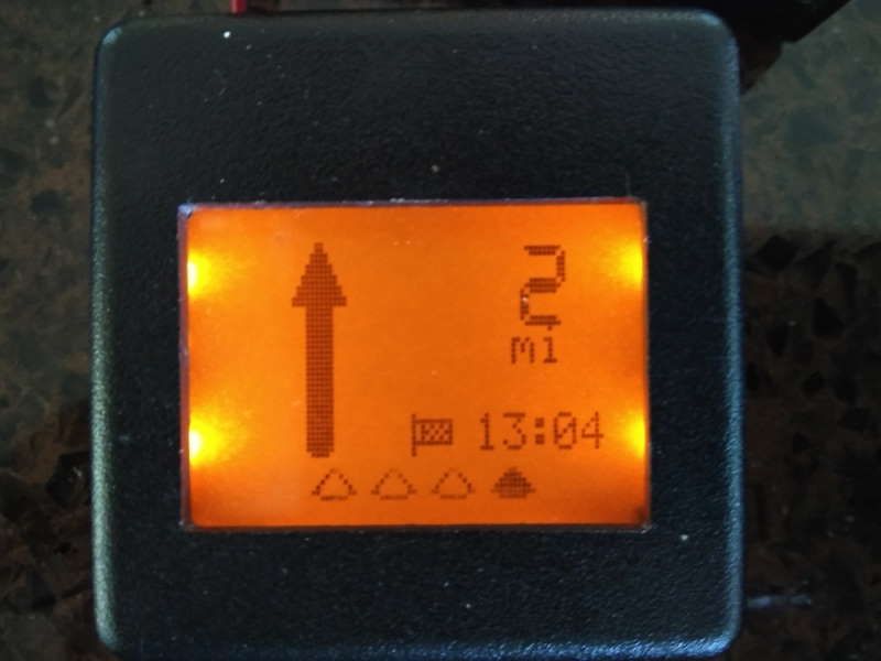

- Direction of next turn.
- Distance to next turn.
- Lane assistance.
- Time to destination.
Hardware selection
The hardware components chosen for this project were selected to meet a very low cost for total bill of materials. This was done as the goal of the device is to be low cost so that it may be left attached to the motorcycle with little regard for theft or damage.
Screen
I chose once more to use the surplus screens from the venerable Nokia 5110 cell phones. These displays are monochrome with a resolution of 84x48. One of the excellent properties of this display are its outstanding contrast in full sunlight environments, which is very important as this is mounted to my motorbike. The backlight supplied with these screens is typically white or blue. I needed to modify the display so the backlight color would match the Suzuki factory LCD backlight color. This is done by removing the 4 SMD LEDs soldered to the back of the board and replacing them with 4 LEDs that are amber colored.
Bluetooth module
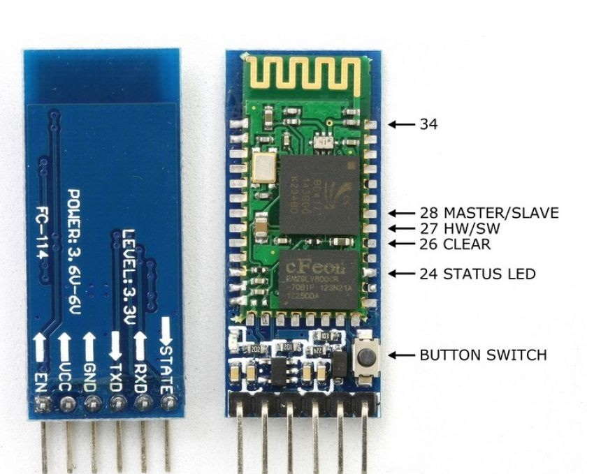
An HC-05 Bluetooth module was ordered from EBay. This item is typically sold as a castellated board soldered to a breakout board with a voltage regulator and level shifter to enable it to interface with an Arduino running @ 3.6-6 volts. For our project we unsoldered the Bluetooth module from the breakout board. Because our circuit is running @ 3.3volts, we don’t need a level shifter or the extra voltage regulator, this has the benefit of reducing our board size as well.
In this image you can clearly see the actual Bluetooth board in green, soldered to the breakout board in blue.
AT Commands
It maybe necessary to program the the Bluetooth module with certain connection parameters using the AT Command set and a serial terminal program. We want to ensure that the module is set to communicate at 9600 baud with 1 stop bit and 1 parity bit.
In order to Set/Check serial parameter of your HC-05 module:
| Command | Respond | Parameter |
|---|---|---|
| AT+UART=<Param>,<Param2>,<Param3> | OK | Param1: Baud Param2: Stop bit Param3: Parity |
| AT+UART? +UART=<Param>, <Param2>, <Param3> | OK | Param1: Baud Param2: Stop bit Param3: Parity |
Example:
AT+UART=9600,1,2,\r\n
OK

AT+UART?
+UART:9600,1,2
OK
Using an Arduino sketch to connect to the Bluetooth module to enter the AT commands
// If you haven't configured your device before use this
#define BLUETOOTH_SPEED 38400 //This is the default baudrate that HC-05 uses
// If you are modifying your existing configuration, use this:
// #define BLUETOOTH_SPEED 57600

#include <SoftwareSerial.h>

// Swap RX/TX connections on bluetooth chip
//   Pin 10 --> Bluetooth TX
//   Pin 11 --> Bluetooth RX
SoftwareSerial BTSerial(10, 11); // RX, TX
void setup()
{
  pinMode(9, OUTPUT);  // this pin will pull the HC-05 pin 34 (key pin) HIGH to switch module to AT mode
  digitalWrite(9, HIGH);
  Serial.begin(9600);
  Serial.println("Enter AT commands:");
  BTSerial.begin(38400);  // HC-05 default speed in AT command more
}

void loop()
{
  // Keep reading from HC-05 and send to Arduino Serial Monitor
  if (BTSerial.available())
    Serial.write(BTSerial.read());

  // Keep reading from Arduino Serial Monitor and send to HC-05
  if (Serial.available())
    BTSerial.write(Serial.read());
}
Power Regulator
The power requirements for this system are only 50mA, the highest current draw was observed from the HC-05 during pairing mode. Typical power draws for the major components breakdown as follows:
| Component | Power mA |
|---|---|
| Display | < 1 mA |
| Backlight | 20mA |
| Bluetooth | 20-50mA |
| Micro Controller | < 1mA |
An LM2937IMP-3.3 linear voltage regulator was selected to provide the power for all the components in my circuit. This is one of the more expensive parts in the system @ $3.40 CAD. It does offer some very cool feature though, handling transient voltages of 60v as well as protection for reverse voltage conditions, internal short circuit protection and thermal overload shutdown. The 3.3 volt variant was selected as this is the voltage specified by the Bluetooth module and the LCD Display controller, the part is rated for up to 400mA however the thermal sinking of our circuit board isn’t up to the task of dissipating the thermal build up at high current loads like this. The only other parts required by our voltage regulator are 2 SMD ceramic capacitors at 0.1 µF and 10 µF.
Micro controller
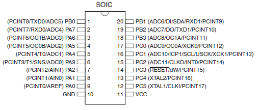
An ATTINY1634R-SU performs the duties of running our code and orchestrating the data between the Bluetooth module and LCD display. This microcontroller (µC) was selected for it’s 16KB of flash memory space and hardware UART port.
Software Design
Protocol decoding
Shout out to Gabriel Valky for his research into decoding the protocol that is used to communicate with the Garmin HUD device. His work documents the message format sent from the Garmin HUD app to the Garmin HUD hardware, see more of his work on GitHub
Run Length Encoded Images
The flash memory on the ATTiny 1634 is not large enough to hold all of the navigation images that are needed to display on the screen. To get around this issue I encoded all of the image arrays using Run Length Encoding. This compresses the image data enough that all of the images would now fit in the program memory space of the micro controller.
RLE encoding works by determining if a byte repeats many times in a sequence, if it does then we write the byte twice followed by a third byte which is the length of this run, note: this means that the max length of a repetitive sequence is 255.
The function for decoding RLE images is very simple, which is another good reason to use it here.
void LcdBitmap(const uint8_t *BMP)
{
  uint8_t col=0, row=0;
  uint8_t data=0,count=0;
  uint16_t i=0;
  uint8_t idx = 0;

  for (row=0; row < 5; row++)
  {
    LcdGotoXY(0, row);
    for (col=0; col < 40; col++)
    {
      if(count==0)
      {
        data = pgm_read_byte(&BMP[i++]);
        if(data==pgm_read_byte(&BMP[i++]))
        {
          count = pgm_read_byte(&BMP[i++]);
        }
        else
        {
          count = 1;
          i--;
        }
      }
      count--;
      screen_buff[idx] |= data;
      idx++;
    }
  }
}
I used a ready made bitmap converter from gabotronics.com to compress the 1 bit bitmaps as RLE encoded arrays that I could then input as resources within the firmware source code. The arrays were stored in program memory directly by decorating them with the PROGMEM macro found in <avr/pgmspace.h>, this also requires that any calls to read the data array are made using the appropriate read macro i.e. pgm_read_byt(&(mydata[i])). The point to using PROGMEM is that we conserve free ram by loading the data resources from the program space rather than loading these variables into memory.
State machine to decode packets
The serial data that is sent from the cell phone to our micro controller comes with no regard to our ability to parse the information or acknowledge its receipt. We may become disconnected from the data stream due to Bluetooth radio interference or simply by re-establishing a communication channel with the sender after an out of range condition. This presents a problem in that we may receive packets that are malformed or may simply pick up a packet half way through its transmission. To solve this I implemented the decoder as a state machine. 
- Receipt of the packet preamble byte sequence
[0x10, 0x7b]transitions to the start packet state. - The packet is buffered in memory until a terminating sequence or pre-amble is encountered.
- The terminating packet sequence will transition the state to End Packet.
- The CRC checksum is calculated and compared to the CRC sent.
- Packet has passed validation and is now acted upon.
- State transitions back to Pre-Amble search.
Hardware Serial Interrupt Routine
I elected to make use of the built in ISR handler ISR(USART0_RX_vect) for the hardware serial port so that normal program execution would be interrupted when ever data was presented to the serial port input. This method is responsible for parsing the incoming data and manipulating the state machine that decodes the input bytes. When message packets are successfully received they are passed to the parse_data() function. The parse_data() function manipulates the global state variables that represent the current navigation direction directive, distance, e.t.a. as well as lane guidance. This global state is later read when the program resumes and is used by the display drawing methods to select the images to place on the LCD at that time.
Circuit
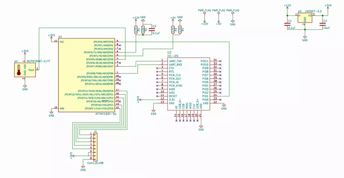
This board layout is created using a single side of the PCB. This made for a simpler build of the printed circuit board at home as there was no need to register a front and back layout in alignment with one another. I find that using a UV light source and pre-sensitized copper clad boards makes for a very clean layout that can be etched reliably.
Putting it all together
The microcontroller was flashed with the program binary files via the ISP interface pins.
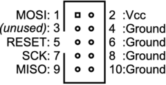
Connected to the corresponding ISP pins on the microcontroller.
After the firmware is flashed to the micro, and components are placed on the PCB. It is time to solder all elements to the board. With a small project like this I find that using the heat from a hot air re-work station along with lots of flux and some fine pitch solder are all that it really needed to flow the components to where they need to be.
After the components are soldered to the board is a great time to test everything out to ensure that it works correctly. Sealing the project in a small abs box and making it waterproof was achieved using hot melt glue (in black of course).
A few more screenshots that demonstrate the final product.