I few months ago I sold my oscilloscope, a very shiny Rigol DS1054Z. If you’ve ever looked into buying an oscilloscope for hobby purposes then you will surely have heard from many people who recommend this mode, for its 50Mhz 4 channel capabilities and its ahem … upgrade ability. While I too was smitten with the new toy at first, it remained shiny a year after its initial purchase as I never really gelled with its UX. Often I would long for a simple scroll bar to move the graph left or right, and I longed to be able to enter triggers by quickly typing values into a keyboard.
It wasn’t long after I sold the Rigol that I found myself needing to record some voltages. My car had developed a miss at idle and I suspected the Mass Air-Flow Sensor was to blame, as the previous owner had installed one of those K&N moar power now! air filters, which can send oil droplets all over your heated MAF wires, thus building up a nice carbon insulation on this finely tuned element of your vehicles fuel injection system.
What I needed was a simple graph of the voltage produced from the MAF sensor so that I could determine if it was reporting correctly at different engine speeds. This sensor as most in the car operate on a DC voltage fed to it from the ECU fixed at a 5volt reference with an independent ground path. The signal from the sensor is a simple varying voltage between the ground and 5 volt reference.
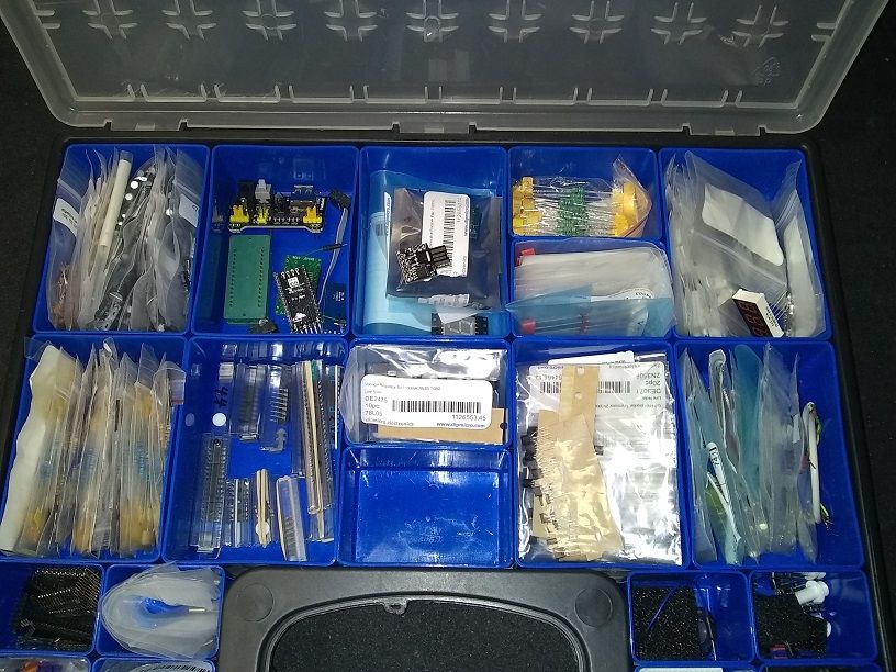
I went fishing in my electronics box and settled on a Digispark.
The Digispark is a cheap and cheerful Arduino compatible board that contains an ATTiny85 micro controller and 5volt regulator. The device implements a USB connection via firmware baked into the boot loader. By implementing the USB controller in firmware the Digispark does not rely on an expensive USB controller chip like the FTDI. This makes our Digispark chip, cheap as well you know … chips. Seriously have a peak on Ebay.
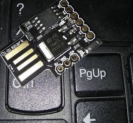 Did I mention these things are small?
Now if you decide to try this at home there are a few caveats to be aware of:
- first off this is not a precision device. The accuracy of the readings is effected by the power regulation supplying the micro controller, in our case a non precision power supply is feeding the controller via our laptops USB port so expected some differences here depending on make and model of the host machine.
- The device offers zero input protection, this is a shortfall that I may address in the future. Vehicles are electrical hell, voltages dip during crank or spike when inductive loads like relays and motors turn off, ignition coils operate at thousands of volts and produce all sorts of noise. You can and probably will feed something nasty through the USB port back to your computer. A good circuit design would include some sort of voltage limiting device to clamp transient spikes.
- Sample rate, the usable sample rate for the ATTiny is in the 10’s of kHz, depending on the clock speed of the micro itself, higher rates will create less accuracy.
- Voltage limit, the input to the ADC should be no higher than the VCC to the micro controller itself. To get around this we could install a voltage divider, but again accuracy will suffer when using inaccurate resistance values or high division ratios.
To setup, you will first need to install the appropriate libraries to allow the Arduino IDE to communicate with the board, the instructions to do this can be found here: install digispark drivers
The code that runs on the device very simply reports back the value contained on the ADC and sends it via the USB port to the host computer. Values are returned as bytes thus the precision is once again sacrificed. The advantage of sending the data this way over say sending a UINT16 is:
- Compactness. This format compresses our values into half as many write calls.
- Simplicity, if we sent two values then we would to produce a prefix scheme so that the receiver could differentiate between a received byte as representing the start of the sequence or the second byte in the sequence. Which in effect means that we increase the message size yet again to accommodate the preamble bytes e.g.
| PREFIX | FIRST | SECOND |
|---|---|---|
| 0x00 | 0x12 | 0x34 |
#include <DigiUSB.h>

void setup() {
  DigiUSB.begin();
}

void loop() {
  DigiUSB.refresh();
  int value = analogRead(1);
  if(value>1020)
    value = 255;
  else if(value<2)
    value = 0;
  else
    value = value/4;
  value = round(byte(value));
  DigiUSB.write(value);
}
p.s. The result of analogRead is a 10bit value. We could and should take advantage of the ATTiny’s ability to return an 8-bit ADC value directly from the ADCH register, provided we set the ADCSRB = (1 << ADLAR); to instruct the ADC that we want our results to be left shifted « 2.
p.p.s. Relying on loop is not a good way to ensure that our ADC is driving the messages into the USB port, may look at performing the writes to USB based on an Interrupt service routine that is called when the ADC sample is filled and thus calls back to our code.
After flashing the firmware to the Digispark the device will begin sampling values on port 0 via the built in analog to digital hardware,
On the host machine I created a windows forms application that connects to the USB endpoint and graphs the values that are received from the micro controller.
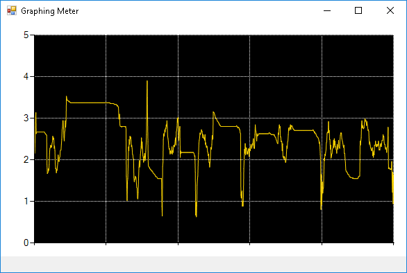
Now I have a tool that can be used to log voltages over time. Hardware cost ~$2. The source code for this can be found on my GitHub Repository.
As for the car, the graph showed that it was over reporting the mass of air pulled into the engine. This information combined with the real time fuel trim data returned from the OBDII port that showed the ECU was removing fuel as a result of the feedback loop from the downstream O2 sensors. Fixing this in my case was simple, replace the Oil laden air filter with the stock paper element. And a gentle cleaning of the MAF sensor elements with a sensor safe solvent spray.