Sometimes you can’t buy the exact thing you want from a store, this is a wonderful opportunity where we can play with some new tools. Let me show you a hardware project where I designed the circuit and coded the firmware so that I could add a gear position indicator to my Motorbike. 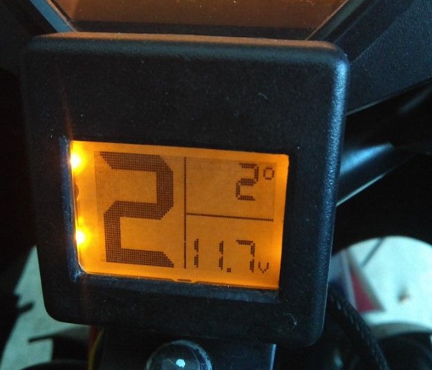
The problem
I have a second generation Suzuki SV650, this is a bike that was built to a budget. Having said that it, you will rarely talk to anyone who has actually ridden this machine and doesn’t have the highest praise for it. There is just something about it that makes the whole greater than the sum of its parts. But I’m never satisfied to just leave good enough alone, and to end there was one thing missing from the old ‘zuki (well two actually, but I won’t go into the suspension modifications here), and that is to say the machine was lacking a gear indicator. I would often find myself banging up for that phantom 7th gear, or worse starting out from a standstill in second. This needs to be fixed.
Attempt to throw money at the problem
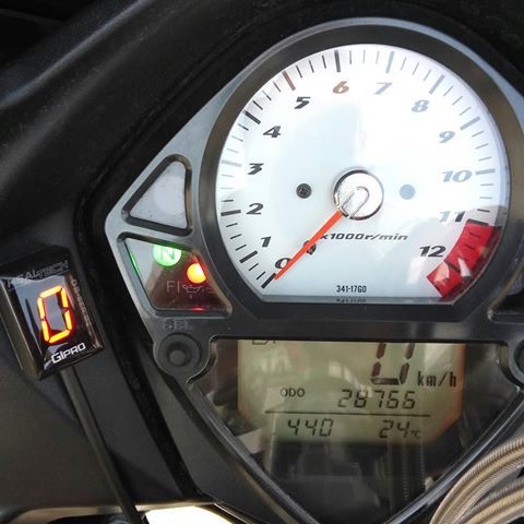
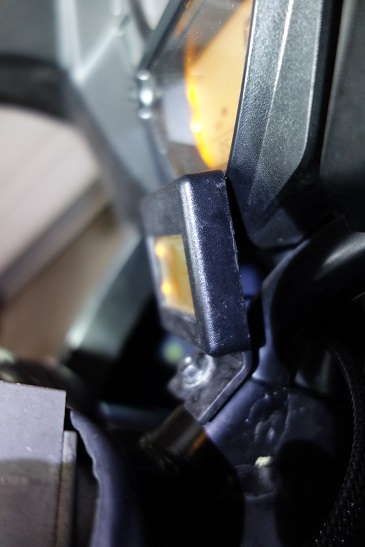
Now there are commercial products out there that can be bought and clipped in place, but I was never keen on the look. See for yourself, the commercial options use a bright (read distracting at night) LED digit. And the display colors don’t mesh with the factory gauges.
The Project Goals
Armed with an idea of what I wanted I set out to achieve the following goals.
- Make a gear position display to interface with the ECU
- Display the voltage of the charging system (the Regulator/Rectifiers on this bike and many others are not noted for their reliability, so having a system to forewarn of failure can keep you from being stranded on the road)
- Display the ambient temperature (and what information!)
The Solution
Choose a uC
I chose to implement my solution with an ATTiny44 micro controller. This particular micro was selected for these reasons.
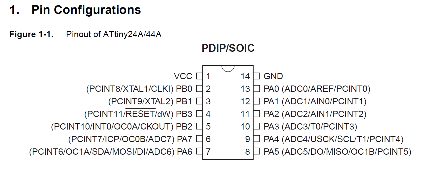
- Small foot print, in SOIC14 packaging it is less than 9mm long while retaining pads large enough to solder by hand
- Low cost, only a few dollars depending on quantity price breaks.
- Amazing tooling Atmel Studio (based on Visual Studio) makes the software writing experience painless
- Samples galore, many of the code samples and libraries used for Arduino development can be modified or at least read for content
- Enough memory for future expansion, an enormous 4K of flash memory combined with 256 bytes of ram ensure we have room to add new features.
- Small power budget @ 3.3volts with a 1Mhz clock our power draw is a fraction of the energy required to power the back light.
Power the board
It has been said before but automobiles are not friendly places for micro electronics. Input voltages can swing wildly, starting conditions, jump starts, ignition components all place havoc. We need a robust power regulator to isolate our design from these pit falls. The LM2937 is 500ma low dropout regulator, I chose to use the SOT-223 package and rely only on the copper of the ground plane as a heat sink. This is safe so long as our current demands are no too taxing. In our case the expected draw is less then 25ma so we have lots of head room.
Display
The display needed to be easily read in direct sunlight, (motorcycles don’t have roofs), And it needed to be monochrome with the ability to be back light in amber (to match to OE instrument cluster). The satisfy these requirements a surplus display from a venerable Nokia 5110 was chosen. This display offers a resolution of 84x48 or 504 bytes of addressable display area.
Temperature Sensing
The temperature sensor did not need to be super accurate as we would be rounding off the precision to the nearest degree Celsius. A MCP9700A was selected for the its reported accuracy of 2 degrees Celsius across a range of 0-70 degrees. Combined with an output that returns 10mv/degree would make the software easier to implement.
The schematic
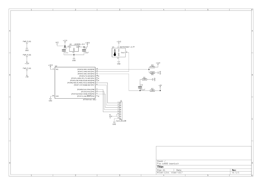
The circuit is powered at 3.3v this is a requirement of the LCD screen as the inputs to its driver are not tolerant of higher input voltages. This means that we have to perform a voltage shift of the incoming signal from the bikes transmission indicator line which outs from 0-5v. A 2:1 voltage divider halves the input voltage to a safe level to feed to the ADC.
A similar voltage divider scheme but at 5.7:1 is used to reduce the voltage value fed in from the power line to a manageable value. This gives our ADC the ability to sample an input voltage as high as 18.8v
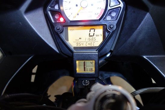
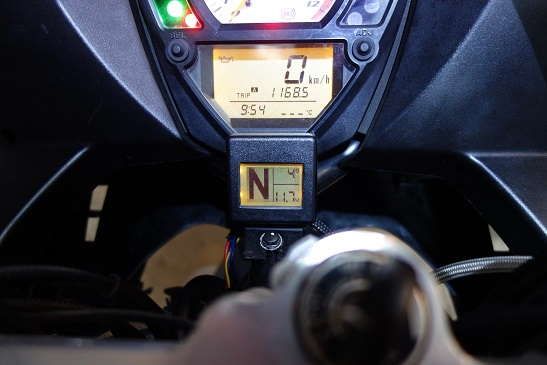
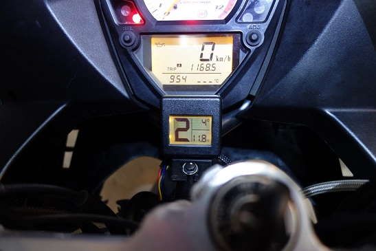
The results
The source code for the firmware as well as the board schematic files can be found on my GitHub Repository